
- Details
- Written by: Keith Norgate
- Category: Gas Extinguishing
- Hits: 370
POSITION YOUR GAS NOZZLE
Distribution and locating gas nozzles to ensure full room coverage of your gas system is one of the most important factors.
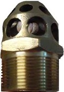
Nozzles
Nozzles are available in 180° and 360° discharge patterns from most suppliers. The 180° (sidewall) nozzle is designed for installation along the walls of the hazard, with the discharge directed away from the wall on which it is installed. The 360° nozzle is designed to be installed in the centre of the area being protected.
CO2 nozzles are also supplied in a variety of styles for local application use.
Design
The hydraulic design programme calculates the size of the nozzle and its orifice size. These are drilled by the supplier and numbered as to the specific place in the pipe network that they must be installed.
Positioning
Nozzles shall be positioned to ensure the design concentration of the gas is achieved in all parts of the enclosure. The velocity of discharge should not adversely affect the enclosure or contents. The rate of discharge can blow loosed items around the room. The rate of discharge should not pose a threat to persons within the protected area.
Ceiling Clearance
Using test protocols nozzles should be placed a maximum of 300mm from the ceiling.
Nozzles must be installed so that the orifices are located close to the ceiling. Ref: SANS 14520 C3.2 a)
Maximum Ceiling Height
A maximum ceiling height when using discharge nozzles is specified by the manufacturer and should be kept to. This is generally around 5m. For hazard volumes higher than 5 meters, an additional row of nozzles is required at ceiling height.
Nozzle Area Coverage
Both the 180° and 360° nozzles will have a maximum coverage distance, these distances will vary for 180° and 360° nozzles. These parameters will show a straight-line distance from the nozzle to the farthest corner of the protected space.
These distances may vary from supplier to supplier and must be checked before installation.
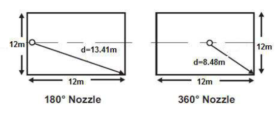
Typical nozzle placement and coverage
180° Nozzles
180° nozzles for either engineered or pre-engineered systems should follow the following rules.
Nozzles must be located from 300mm to 50mm from a wall, with the orifices directed away from the wall. The nozzle shall be located as close to the centre of the wall as possible, but at least 1/3 of the way along the wall.
180° nozzles can be used in a back-to-back configuration.
360° Nozzles
360° Nozzles must be located as close to the centre of the enclosure as possible.
Walls and Obstructions
Chemical agents and CO2 discharged from the nozzle require a certain length from the nozzle to atomize into a gas. If the chemical agent comes into contact with a surface before the agent is fully atomized, frosting can occur. As a result, the concentration throughout the enclosure will be less than the required to appropriately protect the space. Therefore, nozzles must be located at least 1.2 to 1.8 m clearance from walls and/or significant obstructions (e.g. high rise racking and columns).
If this requirement cannot be met, additional agent may be discharged to compensate for this agent “loss”.
Reduced Area Coverage
Consideration should be given to reducing nozzle spacing when obstructions that would impede the uniform distribution of the chemical agent throughout the area are present.
Painting of nozzles
Nozzles must not be painted under any circumstances.
Always check with your supplier the discharge patterns etc of the nozzles supplied before installation.
- Details
- Written by: Keith Norgate
- Category: Gas Extinguishing
- Hits: 514
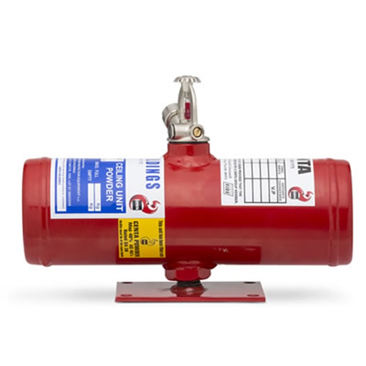
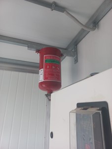
BEWARE!!!
Recently there have been reports of quartzoid bulb operated gas modules being installed in different environments.
Some of them are filled with HFC227 and others with HFC236fa or NAF S227.

Why are we concerned?
1. This type of installation does not comply with any South African standard.
2. We cannot find any approvals on these systems and cylinders.
We can find no tests by any third party authority.
3. HFC227 is a flooding agent and reduces temperature in a closed environment to kill the fire.
HFC 236 is a streaming agent that is not listed in the national standard SANS 14520.
NAF S227 is not listed in the national standard SANS 14520.
4. Most gas standards recommend smoke detection be used for gas suppression systems to ensure the fire is caught at an early enough stage to extinguish the fire. These units require heat (68°C) for them to operate. Heat detectors are not recommended for gas suppression systems.
5. Heat detectors should be within 150mm of the roof for efficient operation. These quartzoid bulbs are generally lower than this distance and some are even lower, mounted on threaded rod brackets.
6. What parameters were used in the design? Was the design based on the operating temperature of the quartzoid bulb 68°C or that of 20°C used for normal room flooding?
7. Recommended maximum operating temperature of gas suppression products according to the national standard is 50°C These units can exceed that when the temperature to burst the quartzoid bulb has to be 68°C.
8. The gas in the cylinder increases in pressure with the rise in temperature and in this case could be as much as 60 bar. These cylinders are not designed to operate at these pressures.
These gasses being discharged at elevated temperatures increase the possibility of breakdown of the gas into hydrogen flouride (HF).
9. With the quantity of gas in these cylinders it can only cover a certain area/volume, is this specified or adhered to? By using more than one module in a room is pointless as the possibility of all quartzoid bulbs reaching the operating temperature at the same time is highly unlikely.
These systems will be offered at a price well below that of a standard gas suppression system BUT will it work or will it be a danger to those who may be in a room at discharge?
CONCERNED - THINK TWICE BEFORE PURCHASING, RECOMMENDING OR INSTALLING THESE UNITS.
- Details
- Written by: Keith Norgate
- Category: Gas Extinguishing
- Hits: 666
The requirement for monitoring of gas cylinders has been in the standards for over 20 years but not often supplied on gas suppression installations, and its importance often overlooked.
When gas is discharged it should produce an alarm to warn personnel immediately and to provide a record of the occurrence.
This is a requirement of the standards (shown below) and should be adopted for all installations.
SANS 369-1 2004: 4.2.1 states:
Confirmation of discharge of fire extinguishing medium should be indicated at the control equipment. The method of deriving the signal should be a pressure or flow switch, located so as to indicate that discharge of gas has occurred from any storage container in the system. For example, in the case of a bank of containers the discharge of gas from any container into the central manifold should be indicated.
The majority of gas cylinders and fire extinguishing control panels supplied in the industry provide this facility and should be connected for all systems.
The inspection bureau have included this onto their checklists for the future.
VISIT www.fireza.net NOW
- Details
- Written by: Keith Norgate
- Category: Gas Extinguishing
- Hits: 739
CO2 gas suppression is still a popular choice for industrial applications, the question is which design method do we use?
Unlike Inerting or Halocarbon agents which have one means of calculation CO2 has four types of calculation to choose between.
- Details
- Written by: Keith Norgate
- Category: Gas Extinguishing
- Hits: 738
A debate is circulating the industry as to why certain gas suppression suppliers use NFPA gas design concentrations in favour of the gas design concentrations in the local SANS / ISO standards which are referenced in SANS 10400:T 2020.
The NFPA 2001- the American based standard for clean agent fire suppression systems requires less gas than the recommended SANS /ISO 14520 equivalent. The overall system would then appear more cost effective to the end user.